
Soot Blower Feed Tube vs Lance Tube: Functions, Differences and Replacement Checks
Feed tubes and lance tubes perform different functions in retractable soot blowers. This guide explains how a stationary feed tube supplies steam or compressed air to a moving lance, why sealing and alignment matter, and which dimensions, materials and interfaces engineers should verify before ordering replacement parts.
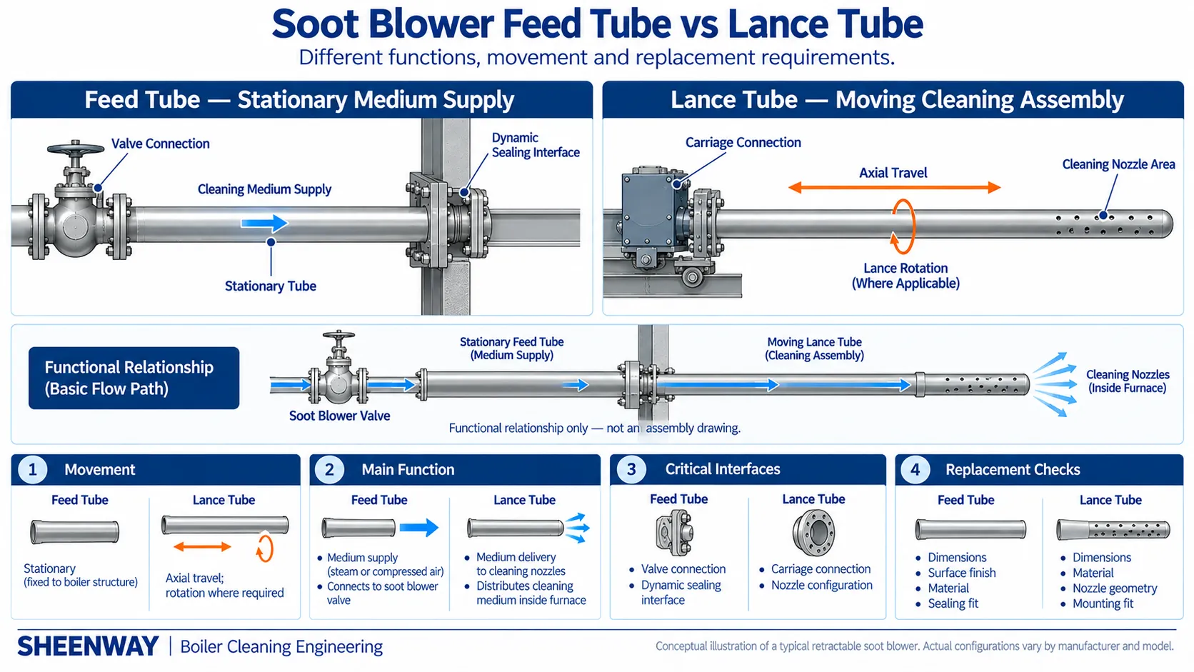
In a retractable soot blower, two tubular components perform different but closely connected functions: the feed tube and the lance tube.
They may both carry steam or compressed air, but their positions, movements, operating environments and replacement requirements are not the same.
The feed tube normally supplies the cleaning medium from the soot blower valve to the moving lance assembly. The lance tube carries that medium toward the nozzle section and moves into the boiler to clean ash deposits from the heating surfaces.
Confusing these components can result in incorrect spare-parts quotations, unsuitable material selection, sealing problems or installation difficulties.
For maintenance engineers and purchasing teams, understanding the difference is therefore essential.
This article explains the working relationship between feed tubes and lance tubes, their typical failure mechanisms, and the technical information required for compatible replacement.
1. What Is a Soot Blower Feed Tube?
A feed tube is the stationary tube that supplies the cleaning medium to the moving lance assembly of a typical retractable soot blower.
Babcock & Wilcox defines the feed tube as the stationary component that delivers cleaning medium to a moving lance tube or rotating element.
In a conventional long retractable arrangement, one end of the feed tube connects to the steam or compressed-air supply through the appropriate soot blower valve and connection assembly.
The other end extends into the moving lance assembly.
When the soot blower operates, the cleaning medium flows through the feed tube and into the lance tube.
The feed tube normally remains fixed relative to the supporting structure while the lance moves.
This arrangement allows steam or compressed air to be delivered to a component that changes position during the cleaning cycle.
In many designs, the feed tube also interacts with a dynamic packing or sealing arrangement.
Consequently, its surface condition, straightness and connection geometry can be important to both medium delivery and sealing reliability.
2. What Is a Soot Blower Lance Tube?
The lance tube is the moving tubular component that delivers the cleaning medium to the nozzle section.
In a conventional long retractable soot blower, the lance travels into the boiler and retracts after cleaning.
It also rotates during the cleaning cycle when the design uses a combined axial and rotary motion.
The cleaning medium exits through nozzles or openings arranged according to the required application.
The resulting cleaning pattern depends on lance movement, nozzle geometry and operating conditions.
Unlike the feed tube, the lance tube may be directly exposed to the boiler's high-temperature, ash-containing flue-gas environment.
Its material and structural design must therefore account for thermal exposure, mechanical loading, corrosion, support and the required cleaning motion.
Not all retractable soot blowers use identical lance movement.
For example, rake-type designs may use non-rotating cleaning assemblies that move axially.
The actual equipment configuration must always be verified.
3. How Do the Feed Tube and Lance Tube Work Together?
The relationship can be understood by following the cleaning medium through the equipment.
Cleaning Medium Supply → Soot Blower Valve → Stationary Feed Tube → Moving Lance Tube → Nozzle Openings → Boiler Heating Surfaces
In a typical long retractable soot blower, the sequence involves several functions.
First, the carriage begins the required movement according to the approved control sequence.
The lance advances toward the boiler gas path.
The blowing-medium valve opens at the specified stage of the operating cycle.
Steam or compressed air flows through the stationary feed tube and enters the moving lance.
The medium then travels toward the nozzle section, where it exits as the cleaning jet.
As the carriage moves, the lance changes position relative to the fixed feed tube.
The sealing arrangement must accommodate this relative motion while controlling leakage.
This is why the relationship between the feed tube, lance connection and packing system is mechanically important.
The feed tube and lance tube form one medium-delivery system, but they do not perform the same mechanical function.
4. Feed Tube vs Lance Tube: Main Engineering Differences
| Engineering Factor | Feed Tube | Lance Tube |
|---|---|---|
| Primary function | Supplies cleaning medium to the moving assembly | Delivers medium to the nozzle section |
| Typical position | Stationary within the soot blower structure | Connected to the moving carriage |
| Movement | Usually stationary | Axial travel; rotation when required |
| Boiler exposure | Usually outside the primary gas path | May enter the hot flue-gas region |
| Nozzle openings | Normally not the main cleaning-nozzle component | Carries the cleaning nozzles or openings |
| Sealing function | Provides a mating surface for dynamic sealing in many designs | Connected to the moving sealing and drive arrangement |
| Main engineering concerns | Surface finish, sealing, corrosion, dimensions and alignment | Thermal resistance, strength, straightness, corrosion, nozzle configuration and connections |
| Replacement focus | Feed and sealing interfaces | Cleaning and mechanical interfaces |
These characteristics describe common retractable soot blower arrangements.
They should not be treated as a complete specification for every manufacturer or model.
5. Why Feed Tube Surface Condition Matters
The feed tube may appear mechanically simple, but its external surface can be important.
In designs where a packing assembly moves relative to the feed tube, the tube surface participates in the sealing interface.
A damaged or unsuitable surface may increase packing wear, compromise sealing performance or contribute to excessive friction.
Potential concerns include:
- Surface scratches or scoring.
- Localized corrosion.
- Loss of required straightness.
- Damage to the tube ends or connections.
- Wear in the packing contact region.
- Incorrect alignment with the moving carriage.
For example, historical long retractable soot blower documentation used by SHEENWAY describes a polished stainless-steel feed tube connected to the soot blower valve.
EPRI's sootblower maintenance guidance also identifies feed-tube surface condition as an important consideration in certain retractable designs.
However, this does not mean every feed tube must use the same stainless-steel grade, polishing method or specified surface roughness.
The actual requirement depends on the original equipment and its sealing design.
A replacement feed tube must be evaluated as a functional sealing and medium-delivery component, not simply as a length of metal pipe.
6. Why Lance Tube Material and Geometry Matter
The lance tube faces a different set of engineering challenges.
When inserted into the boiler, it may experience elevated gas temperatures, ash exposure and mechanical loads.
The lance is also supported over a relatively long distance compared with its diameter.
Its condition depends on factors including:
Material Selection
The material must meet the application requirements for temperature, strength, corrosion resistance and fabrication.
Straightness and Support
The lance must maintain appropriate alignment and clearance throughout its intended movement.
Nozzle Geometry
Nozzle quantity, diameter, position and orientation affect the cleaning pattern.
Mechanical Connection
The lance must correctly connect to the carriage and related components.
Thermal Exposure
The operating sequence and retracted position influence how long the lance remains exposed to boiler conditions.
Babcock & Wilcox identifies different lance materials and support arrangements as important features of retractable soot blowers.
SHEENWAY's SW-SLRG documentation similarly states that nozzle dimensions, travel, rotation and blowing-medium requirements depend on the boiler conditions.
Therefore, the lance should be selected using its actual operating requirements rather than only the nominal pipe size.
7. How Packing and Sealing Connect the Two Components
The interface between a stationary feed tube and a moving lance assembly requires special attention.
In many retractable soot blower designs, a packing system allows the moving assembly to travel—and, where applicable, rotate—while limiting the escape of steam or compressed air.
The exact location and construction of the sealing assembly depend on the equipment model.
A typical arrangement may include a packing chamber, packing rings, a gland and associated support components.
Several problems can develop if this interface is unsuitable.
Excessive packing compression
May increase friction and motor loading.
Insufficient sealing
May lead to blowing-medium leakage.
Feed-tube surface damage
May accelerate wear of the interacting packing surfaces.
Mechanical misalignment
May produce uneven contact, wear or leakage.
Replacement of a feed tube should therefore consider the mating packing arrangement.
Similarly, replacement of a lance assembly should include review of its connection to the moving hub and sealing system.
Matching the tube diameter alone does not establish sealing compatibility.
8. Common Feed Tube Problems
A feed tube may require investigation when the equipment shows abnormal sealing performance or mechanical wear.
Possible observations include:
Steam or Air Leakage
Leakage may occur around the packing interface or associated connections.
Surface Scoring
Longitudinal scratches or localized damage may indicate contact, contamination or alignment problems.
Corrosion
Material deterioration may affect wall condition and the sealing surface.
Abnormal Packing Wear
Repeated packing problems may indicate unsuitable feed-tube surface condition, misalignment or incorrect installation.
Mechanical Distortion
A bent or improperly supported feed tube can affect its interaction with the moving assembly.
These symptoms are not proof that the feed tube itself is defective.
Other components, including the carriage, seals, supporting structure and installation alignment, may contribute.
The complete interface should be inspected before deciding which part requires replacement.
9. Common Lance Tube Problems
Lance tube problems often have a different operating pattern.
Potential issues include:
- Permanent bending or thermal distortion.
- Localized corrosion or erosion.
- Damage near the nozzle region.
- Cracking or deterioration at welded connections.
- Abnormal contact with support rollers or wall-box components.
- Difficulty extending or retracting.
- Changes in nozzle condition or orientation.
The cause may involve temperature exposure, mechanical support, material condition, operating sequence or other factors.
A visibly bent lance should not automatically be replaced without investigating the support and alignment conditions.
Likewise, damage near a nozzle should be evaluated in relation to the original nozzle geometry, steam conditions and operating history.
An incorrect replacement could reproduce the same problem.
10. What Should Be Checked Before Ordering a Feed Tube?
A replacement feed tube should be specified using the original equipment design and verified site information.
The following details are useful.
| Required Information | Why It Matters |
|---|---|
| OEM manufacturer and soot blower model | Identifies the original design |
| Feed-tube part number | Identifies the intended component |
| Outside diameter | Defines sealing and assembly interfaces |
| Wall thickness or inside diameter | Defines basic tube geometry |
| Overall length | Establishes physical compatibility |
| Material grade and standard | Supports service-condition review |
| Surface finish requirements | Supports packing and sealing compatibility |
| Straightness requirement | Supports alignment and movement |
| Valve-end connection | Confirms inlet compatibility |
| Discharge-end geometry | Confirms connection to the moving assembly |
| Packing and gland configuration | Confirms sealing compatibility |
| Original drawings, photos or sample | Supports dimensional verification |
A polished appearance alone does not establish compliance with a specified surface-finish requirement.
If a particular roughness value is required, it should come from the original specification or an approved engineering design.
Likewise, a material grade should not be guessed from appearance.
11. What Should Be Checked Before Ordering a Lance Tube?
For a replacement lance tube, the critical requirements are different.
| Required Information | Why It Matters |
|---|---|
| OEM manufacturer, model and part number | Identifies the original lance |
| Outside diameter and wall thickness | Defines structural geometry |
| Total length | Establishes component dimensions |
| Material grade and standard | Supports thermal and corrosion review |
| Nozzle quantity and size | Defines cleaning-medium discharge |
| Nozzle position and orientation | Defines cleaning direction |
| End cap and nozzle-section geometry | Confirms the original cleaning-end arrangement |
| Carriage or hub connection | Confirms mechanical compatibility |
| Required stroke | Relates the lance to equipment movement |
| Travel and rotation characteristics | Supports functional compatibility |
| Boiler installation zone and temperature | Defines the operating environment |
| Original drawings, photos or sample | Supports verification |
SHEENWAY has already published a detailed guide covering the ten main specifications for replacement lance tubes.
That guide should be used alongside this article when preparing a lance-tube inquiry.
The important distinction is that feed-tube procurement focuses strongly on medium delivery and sealing, while lance-tube procurement must also address the cleaning-end geometry and boiler operating conditions.
12. Can the Feed Tube and Lance Tube Use Different Materials?
Yes. Depending on the original design, the components may use different materials because their operating conditions are different.
A feed tube is typically located within the external soot blower structure and may require particular corrosion resistance and sealing-surface properties.
A lance tube can enter a hotter gas path and may require additional temperature and mechanical-strength considerations.
However, this does not establish one universal material combination.
The selected materials must be confirmed against the actual original equipment specification and operating conditions.
A stainless-steel feed tube and an alloy-steel lance tube may be appropriate for certain designs, but the exact grades cannot be selected solely from that general description.
Material substitution requires an engineering review.
For replacement projects, the original material specification, traceability documents and service environment should be checked whenever available.
13. How to Identify Which Tube the Customer Actually Needs
International inquiries often describe the required part simply as a “soot blower tube.”
This creates ambiguity.
The first question should be whether the customer requires a stationary feed tube or a moving lance tube.
Useful identification clues include:
Component location
Is the tube part of the fixed steam-supply arrangement or the moving cleaning assembly?
Nozzle configuration
Does the component contain the original cleaning-nozzle section?
Connection
Does it connect to the valve, carriage hub or another assembly?
Movement
Does it remain stationary or travel with the carriage?
Sealing interface
Does it interact directly with packing or other dynamic seals?
These observations help identify the component, but an accurate determination should use drawings, part numbers or verified original-equipment information when available.
For ambiguous quotations, the buyer should label the requested components separately as:
Feed Tube Assembly
and
Lance Tube Assembly
rather than grouping both under a generic “soot blower pipe” description.
14. Why Cross-Brand Replacement Requires Technical Verification
A replacement component does not necessarily have to come from the original equipment manufacturer.
However, successful replacement requires the correct technical definition.
SHEENWAY supports the manufacture of OEM-compatible replacement components, including parts designed to match verified Clyde Bergemann and Diamond Power specifications.
For a one-to-one replacement, the dimensional and functional requirements must be established from the corresponding original equipment.
This may involve original part identification, available technical drawings, verified measurements, material specifications and inspection of representative components.
The replacement should reproduce the required interfaces and operating functions.
However, a feed tube or lance tube designed for one soot blower model must not be assumed to fit every model from the same manufacturer.
Different design generations may use different connections, diameters, sealing arrangements or movement requirements.
The manufacturer's name is an identification starting point, not a substitute for engineering verification.
15. Replacement Inspection and Installation Considerations
Before installing a new feed tube or lance tube, the replacement should be checked against the approved technical specification.
Depending on the component, inspection may include:
- Material identification and supporting documentation.
- Outside diameter, wall thickness and overall length.
- Straightness and visible surface condition.
- End connections and mounting interfaces.
- Nozzle dimensions and orientation, where applicable.
- Packing and sealing interfaces.
- Compatibility with the carriage and supporting structure.
- Relevant manufacturing and inspection records.
Installation and functional checks must follow the approved equipment and plant procedures.
Work on a steam soot blower must not begin before the required electrical, pressure and other hazardous-energy isolation measures are completed.
A feed tube with the correct dimensions but damaged sealing surfaces may not function properly.
Likewise, a lance tube that fits the carriage but has an incorrect nozzle orientation may not reproduce the intended cleaning pattern.
Both dimensional and functional conformity are necessary.
Conclusion
Feed tubes and lance tubes are separate components with different engineering functions.
The feed tube is normally the stationary component that supplies steam or compressed air to the moving lance assembly.
The lance tube carries the cleaning medium to the nozzle section and moves through the required cleaning area.
Their replacement requirements reflect these differences.
Feed-tube compatibility depends heavily on dimensions, surface condition, valve connections and dynamic sealing interfaces.
Lance-tube compatibility additionally depends on material, thermal exposure, structural support, nozzle geometry, mechanical connections and movement.
A correctly specified replacement must match the function of the original component—not simply its nominal pipe dimensions.
SHEENWAY provides customized feed tubes, lance tubes and other compatible soot blower spare parts based on verified original equipment specifications and application requirements.
For technical evaluation, customers are encouraged to provide the original equipment model, part number, relevant dimensions, operating conditions and available reference photographs or drawings.
More from Sheenway
Continue Reading
Soot Blower Commissioning Checklist: From Cold Tests to Hot Operation
Commissioning a soot blowing system requires more than checking motor operation. This guide covers pre-start inspection, mechanical alignment, steam piping, drainage, electrical controls, cold functional testing, hot commissioning and final acceptance for reliable boiler soot blower operation.
Read articleSoot Blower Steam Piping Thermal Expansion: Supports, Flexibility and Connection Loads
Thermal expansion in soot blower steam piping can impose unintended loads on valves, flanges and equipment connections. This guide explains pipe flexibility, anchors, guides, supports, expansion compensation and drainage considerations for reliable boiler soot blowing systems.
Read articleSoot Blower Steam Consumption and Header Sizing: What Engineers Should Verify
Steam soot blowing systems must supply the required pressure and mass flow to each operating blower. This guide explains how individual steam consumption, simultaneous demand, header sizing, pressure drop, drainage and control sequencing affect steam supply system design and retrofit decisions.
Read article