
Soot Blower Steam Piping Thermal Expansion: Supports, Flexibility and Connection Loads
Thermal expansion in soot blower steam piping can impose unintended loads on valves, flanges and equipment connections. This guide explains pipe flexibility, anchors, guides, supports, expansion compensation and drainage considerations for reliable boiler soot blowing systems.
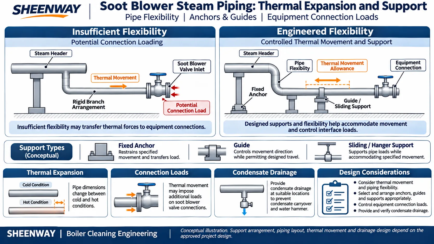
Steam soot blowing systems are often evaluated in terms of steam pressure, flow rate, nozzle performance and control sequencing. However, the mechanical behavior of the steam distribution piping is equally important.
When steam piping heats up from its installed condition to operating temperature, it expands. As the system cools, it contracts.
These movements are normal, but they must be accommodated by the piping design.
If thermal movement is excessively restrained, additional forces and moments can develop at pipe supports, branch connections, flanges and equipment interfaces.
For a soot blowing system, this is particularly important near the connections to individual soot blower valves.
A pipe that appears correctly aligned during cold installation may impose unintended loads on the equipment after the boiler reaches operating temperature.
Reliable soot blower piping design must accommodate thermal movement while maintaining adequate support, drainage, pressure integrity and equipment connection compatibility.
This article explains the principles of steam-pipe thermal expansion, the functions of anchors and guides, the selection of flexibility arrangements and the inspections required during installation or retrofit.
1. Why Does Steam Piping Expand?
Metal piping changes dimensions when its temperature changes.
During installation, steam pipes are normally assembled at a temperature considerably below their eventual operating temperature.
When the system is heated, the pipe material expands.
For a straight pipe with approximately uniform temperature, the change in length can be estimated using the basic linear thermal-expansion relationship:
ΔL ≈ α × L × ΔT
Where:
- ΔL = estimated change in pipe length;
- α = coefficient of linear thermal expansion for the pipe material;
- L = original pipe length;
- ΔT = temperature change of the pipe material.
This relationship illustrates the main physical principle.
It does not replace a complete piping flexibility or stress analysis.
Actual pipe movement depends on the material, temperature distribution, pipe geometry, restraints, connected equipment and supporting structure.
A long straight run may experience a greater overall dimensional change than a short run of the same material operating over a similar temperature range.
However, the resulting mechanical loads depend on how the movement is accommodated.
Thermal expansion itself is not a defect. The engineering concern is excessive restraint or unsuitable transfer of the resulting loads.
2. Why Thermal Expansion Matters to Soot Blower Connections
Soot blower steam piping connects the plant steam distribution system to individual cleaning devices.
Depending on the installation, a branch may terminate at a soot blower valve, supply connection or another approved interface.
These equipment connections are not intended to serve automatically as fixed anchors for the entire upstream pipe network.
If the branch cannot accommodate the relative movement between the steam header and the soot blower, thermal forces and moments may be transmitted into the equipment.
Possible consequences include:
- Additional loading on valve bodies and connections.
- Flange alignment problems.
- Gasket-sealing difficulties.
- Stress on branch connections or welded joints.
- Distortion of adjacent piping.
- Interference with equipment installation or maintenance.
These effects are possible consequences, not proof that any observed leak or distortion was caused by thermal expansion.
SHEENWAY's existing soot blowing piping documentation specifically requires sufficient flexibility at the connection to the soot blower valve to avoid excessive external forces that could affect valve sealing and equipment operation.
The objective is to support the piping independently while keeping equipment connection loads within the applicable design limits.
3. Cold Alignment Does Not Guarantee Hot Alignment
A common installation misunderstanding is that a pipeline is acceptable once its flanges align correctly at ambient temperature.
Cold fit-up is important, but it represents only one operating condition.
During startup, the steam piping heats and expands.
At the same time, the boiler structure and the soot blower supporting arrangement may undergo their own thermal movements.
These movements are not necessarily equal or in the same direction.
Consequently, the relative position of a branch connection and the soot blower valve can change between cold and hot operating conditions.
A well-designed arrangement must consider the relevant relative movement.
Potential problem areas include:
- Long branches connected to fixed equipment.
- Pipe runs crossing between different structural supports.
- Connections near boiler casing movement.
- Branches exposed to different temperature conditions.
- Piping with incorrectly positioned or seized supports.
An apparently well-aligned cold flange should not be used as the sole basis for accepting the entire thermal design.
4. The Different Functions of Anchors, Guides and Supports
The terms anchor, guide and support describe different mechanical functions.
They should not be treated as interchangeable.
Fixed Anchors
An anchor restrains the specified movements and transfers the corresponding forces and moments into the supporting structure.
Anchors establish reference positions within the piping system.
Their location strongly influences the direction of thermal movement and the load distribution.
Guides
A guide controls movement in selected directions while permitting the motion allowed by its design.
For example, an appropriately designed guide may maintain pipe alignment while allowing axial thermal expansion.
Sliding Supports
A sliding support carries pipe weight while allowing specified movement along its supporting surface.
Its actual performance depends on factors including friction, loading and mechanical condition.
Hangers and Other Supports
Hangers and other support devices carry the required pipe loads.
Depending on their design, they may accommodate movement or apply a controlled supporting force over a movement range.
The correct support arrangement depends on the complete piping geometry.
Adding more restraints without engineering review can increase thermal stress rather than improve reliability.
5. Natural Pipe Flexibility: The First Design Consideration
Not every steam line requires a dedicated expansion joint.
A suitably designed piping route may have enough natural flexibility to accommodate expected thermal movement.
Bends, changes in direction and available pipe length can contribute to this flexibility.
For example, a branch with an appropriately designed offset may accommodate movement differently from a short, rigidly restrained straight connection.
However, adding arbitrary bends does not automatically make a pipeline safe.
The arrangement must be evaluated for:
- Thermal displacement.
- Sustained loads.
- Operating pressure.
- Pipe material and temperature.
- Support reactions.
- Equipment connection loads.
- Available installation space.
- Drainage and maintenance requirements.
The required flexibility must be established through the applicable engineering design process.
A pipe route should not be altered solely to make installation easier if the change has not been evaluated for movement and support requirements.
6. Expansion Loops and Engineered Flexibility
Where natural pipe flexibility is insufficient, an engineered flexibility arrangement may be required.
One option is an expansion loop constructed from suitable pipe sections and elbows.
The geometry allows the piping to deform elastically under the intended thermal movement.
Expansion loops may be useful where sufficient space is available.
However, their design must account for the actual movement, pressure, temperature, support arrangement and permissible stresses.
An expansion loop also affects pipe routing and potentially the distribution-system pressure loss.
It should not be inserted into an existing steam line without engineering evaluation.
The presence of a U-shaped pipe does not automatically prove that an adequate expansion loop has been designed.
Loop dimensions and orientations must be determined for the specific installation.
7. When Are Expansion Joints Required?
Some steam piping systems use purpose-designed expansion joints, including metallic bellows assemblies, to accommodate specified movements.
Whether an expansion joint is appropriate depends on the required movement, available space and piping stress analysis.
Its selection may require review of:
- Design pressure and temperature.
- Expected axial, lateral or angular movement.
- Pressure thrust.
- Anchor and guide capacity.
- Cyclic operating conditions.
- Installation orientation.
- Relevant manufacturer requirements.
An expansion bellows is not a substitute for correctly designed anchors and guides.
Internal pressure can create forces that must be addressed in the surrounding piping system.
Incorrect restraint or alignment can damage the expansion joint or connected equipment.
Expansion joints must be selected and installed as engineered components, not treated as universal flexible connectors.
In some applications, natural piping flexibility or an engineered pipe loop may be more suitable.
The correct choice must be established by the project design.
8. Boiler Thermal Movement and Supporting Structures
Soot blower piping is installed around boiler structures that may experience substantial temperature changes.
Boiler casing, wall structures, supporting steel and connected equipment may move relative to one another.
The piping support arrangement must take these movements into account.
Depending on the installation, pipe supports may be attached to:
- Approved boiler structural members.
- Supporting steel frames.
- Platforms or structural beams.
- Other engineered support locations.
The attachment point must be structurally suitable and compatible with the expected movement.
A support should not be added to a convenient nearby member without checking the load path.
The relative movement between a hot boiler structure and a separate, cooler supporting frame may be particularly important.
For these reasons, pipe-support design should be coordinated with the boiler general arrangement and relevant structural information.
9. Why Branch Piping Needs Special Attention
The interface between the distribution header and an individual soot blower deserves particular review.
The branch should provide the required steam capacity while accommodating the mechanical relationship between its connection points.
Potential concerns include:
Unsupported Pipe Weight
An inadequately supported branch may transmit unnecessary deadweight loads to the soot blower valve.
Thermal Displacement
Movement of the header or boiler structure may create additional loads at the branch connection.
Rigid Connection Geometry
A short, fully restrained branch may have insufficient flexibility for the actual relative movement.
Support Interference
A seized sliding support or incorrectly positioned guide may prevent the intended pipe movement.
Maintenance Modifications
Replacement of a valve or spool piece may change the connection geometry and load distribution.
The correct solution is not necessarily to add an expansion joint immediately before every soot blower.
It is to evaluate the branch, supports, movement and equipment interface as a system.
10. Thermal Expansion and Condensate Drainage Must Be Considered Together
Steam piping must allow appropriate thermal movement without creating unacceptable condensate accumulation.
A poorly arranged flexibility loop or expansion component can create local low points where condensate collects.
The drainage condition may also change as supports move and the piping reaches operating temperature.
This is particularly relevant to intermittently operated soot blowing systems.
During standby periods, steam piping may cool.
Condensate may then form or collect in portions of the network.
When the system is warmed up again, inadequate drainage can increase the risk of liquid carryover and water hammer.
The piping layout should therefore coordinate:
- Thermal flexibility.
- Pipe support and movement.
- Required drainage gradients.
- Engineered collection points.
- Drainage equipment.
- Startup and warm-up procedures.
There is no single drainage slope or fixed expansion-loop configuration that should be copied into every installation.
Both thermal movement and condensate management must follow the actual approved piping design.
11. Common Signs of Thermal or Support-Related Problems
The following observations may justify further inspection.
| Observed Condition | Possible Contributing Factors | Initial Engineering Review |
|---|---|---|
| Repeated flange leakage | Connection loading, gasket condition or assembly problems | Flange condition and pipe reactions |
| Pipe distortion after startup | Thermal restraint, support problems or unsuitable routing | Hot/cold geometry and support movement |
| Abnormal movement at a branch | Differential thermal movement or inadequate restraint | Branch geometry and support design |
| Expansion joint damage | Incorrect movement, anchoring or pressure-thrust restraint | Joint rating, installation and adjacent supports |
| Support displacement or damage | Incorrect load transfer, travel or structural condition | Support loading and attachment |
| Local condensate accumulation | Inadequate drainage geometry or changed pipe position | Drainage points and hot/cold slope |
| Recurring connection misalignment | Relative movement or inappropriate field modification | Interface dimensions and thermal displacement |
These symptoms are not unique to thermal expansion.
For example, flange leakage may also originate from damaged gaskets, incorrect assembly or deterioration of the sealing surfaces.
The actual cause should be confirmed before modifying supports or changing the piping route.
12. Inspection During Cold and Hot Conditions
Where appropriate and permitted by the plant procedures, engineers can compare relevant piping conditions during installation, startup and normal operation.
Cold-condition inspections may include:
- Pipe and support identification.
- Anchor and guide positions.
- Visible alignment of approved connections.
- Expansion-device installation condition.
- Available movement clearances.
- Drainage and support geometry.
- Evidence of unauthorized modifications.
Hot-condition reviews may include:
- Observable movement at designated supports.
- Changes in piping position.
- Unexpected leakage.
- Abnormal vibration.
- Interference with adjacent structures.
- Expansion-device condition where externally observable.
Any hot-condition assessment must use safe, approved observation methods.
Personnel must not touch, loosen, adjust or disassemble pressurized hot piping or supports to investigate movement.
Measurements requiring intrusive access should be performed only under the appropriate isolation and safety procedures.
13. What Information Is Needed for a Piping Flexibility Review?
An engineering review requires more than a photograph of the affected pipe.
Useful information includes:
| Required Information | Engineering Purpose |
|---|---|
| Piping layout and isometric drawings | Identify geometry and routing |
| Design and operating temperatures | Establish relevant thermal conditions |
| Design and operating pressures | Evaluate pressure-related requirements |
| Pipe dimensions and materials | Establish mechanical characteristics |
| Support and anchor locations | Define restraint and load paths |
| Guide and hanger details | Evaluate permitted movement |
| Expansion-joint specifications, if installed | Check movement and pressure-thrust requirements |
| Boiler structural movement information | Assess relative displacement |
| Soot blower valve connection details | Confirm equipment interfaces |
| Allowable equipment connection loads | Evaluate forces and moments |
| Drainage layout | Check condensate management |
| Operating and maintenance records | Identify recurring problems |
The applicable piping code and project specifications must be established before final design verification.
For power-generation piping within its scope, ASME B31.1 is one relevant standard.
The required edition, applicable provisions and project-specific acceptance criteria must be confirmed by the responsible engineering team.
This article is not a substitute for formal piping stress analysis.
14. What Should Be Checked During a Soot Blower Retrofit?
A soot blower replacement project may change the mechanical relationship between the steam branch and the equipment.
Even when a replacement soot blower fits the original mounting arrangement, its valve connection position or interface geometry may differ.
A retrofit review should consider:
- Existing branch routing.
- Original and replacement valve connection positions.
- Pipe deadweight support.
- Expected thermal movement.
- Existing anchors and guides.
- Expansion compensation arrangement.
- Drainage requirements.
- Installation and maintenance clearances.
- Any modifications to boiler structural attachments.
If the existing piping must be modified, the changes should be evaluated against the approved piping design requirements.
A field adjustment that forces two flanges into alignment should not be accepted as evidence of correct mechanical compatibility.
The completed arrangement must remain suitable under the relevant operating conditions.
SHEENWAY has documented soot blower retrofit projects involving steam pressure reduction, distribution piping, expansion compensation and pipe supports.
Such projects illustrate why a complete soot blowing installation must be reviewed beyond the soot blower body alone.
15. Installation and Commissioning Considerations
A correctly designed pipe system still requires appropriate installation and verification.
Depending on the project, commissioning checks may include:
- Confirming pipe and support installation against approved drawings.
- Verifying anchors, guides, sliding supports and hangers.
- Inspecting expansion joints where specified.
- Confirming valve and equipment connection alignment.
- Checking drainage arrangements and low-point collection.
- Completing the required pressure-system inspection and testing.
- Verifying suitable pipe movement during approved warm-up.
- Monitoring relevant connections for leakage or abnormal behavior.
- Recording observed discrepancies for engineering assessment.
Pressure testing and steam-system startup must follow the applicable approved procedures.
Supports or expansion components must not be relocated, removed or adjusted arbitrarily after commissioning.
Changes to the piping restraint system can alter the distribution of forces and moments throughout the network.
Conclusion
Thermal expansion is a normal characteristic of steam piping, but the resulting movement must be addressed in the engineering design.
For soot blowing systems, the most important concerns include the loads transmitted into individual soot blower connections, the behavior of anchors and guides, the adequacy of piping flexibility and the interaction between thermal movement and condensate drainage.
Natural pipe flexibility, engineered expansion loops and specialized expansion joints may all have roles in an appropriate design.
None should be selected without considering the complete piping system.
Reliable soot blower steam piping must be supported where required, allowed to move where designed, and prevented from imposing unacceptable loads on connected equipment.
SHEENWAY supports soot blowing steam distribution projects, equipment interface verification and retrofit engineering based on confirmed boiler and piping requirements.
For technical review, customers can provide the existing piping drawings, operating conditions, support arrangements and soot blower connection details.
More from Sheenway
Continue Reading
Soot Blower Commissioning Checklist: From Cold Tests to Hot Operation
Commissioning a soot blowing system requires more than checking motor operation. This guide covers pre-start inspection, mechanical alignment, steam piping, drainage, electrical controls, cold functional testing, hot commissioning and final acceptance for reliable boiler soot blower operation.
Read articleSoot Blower Steam Consumption and Header Sizing: What Engineers Should Verify
Steam soot blowing systems must supply the required pressure and mass flow to each operating blower. This guide explains how individual steam consumption, simultaneous demand, header sizing, pressure drop, drainage and control sequencing affect steam supply system design and retrofit decisions.
Read articlePositive-Pressure Boiler Wall Boxes: Sealing Air, Design and Common Problems
Positive-pressure boiler wall boxes help control flue-gas leakage around soot blower lance penetrations. This guide explains sealing-air principles, differences between positive- and negative-pressure arrangements, common faults and the engineering checks required for installation, maintenance and replacement.
Read article