
Soot Blower Control Interlocks: Limit Switches, Valve Timing and DCS Integration
Soot blower control interlocks coordinate lance movement, travel-limit switches, blowing-medium valve timing and PLC/DCS signals. This technical guide explains start permissives, operating sequences, fault responses and commissioning checks for reliable retractable soot blower operation.
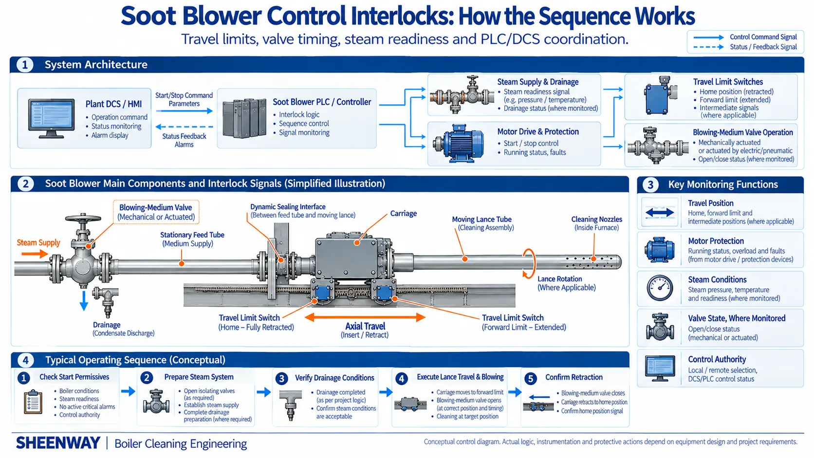
A retractable soot blower is not simply a motor-driven cleaning device. It is part of a coordinated system involving mechanical movement, blowing-medium supply, position monitoring and electrical control.
During a normal cleaning cycle, the lance must advance, deliver the cleaning medium at the appropriate stage, reach its intended travel position, reverse and return to standby.
These actions must occur in the correct relationship to one another.
If a position signal is missing, a motor becomes overloaded or the blowing-medium conditions are unsuitable, the control system must respond according to the approved equipment and plant protection requirements.
This is the purpose of soot blower control interlocks.
Effective interlocking coordinates equipment movement, valve operation, operating permissions and fault responses rather than simply switching the motor on and off.
This guide explains the main control principles for retractable steam soot blowers, including travel-limit switches, valve timing, PLC logic and DCS integration.
1. What Is a Soot Blower Control Interlock?
A control interlock is a defined relationship between an equipment condition and an allowed or required control action.
In a soot blowing system, interlocks help prevent operations from proceeding when specified conditions have not been satisfied.
They can also trigger a defined response when an abnormal condition develops during operation.
For example, a control system may require confirmation that a soot blower is available, its motor protection is healthy and the required steam-supply conditions have been established before allowing an automatic cleaning cycle.
During operation, the system may monitor travel position, motor status and operating time.
If the expected response does not occur, the controller can generate an alarm and execute the applicable fault-handling sequence.
The precise logic depends on the soot blower type, mechanical arrangement, steam system and plant-approved control philosophy.
An interlock should therefore be treated as an engineered operating function, not a universal set of software conditions that can be copied between projects.
2. Main Components of a Soot Blower Control System
A centralized soot blowing system may contain several interacting elements.
Local Electrical Equipment
Motor connections, contactors, protection devices, field switches and local operating controls provide the equipment-level interface.
Travel-Position Devices
Limit switches or other approved position-detection devices provide information about the lance and carriage position.
Blowing-Medium Equipment
Isolation valves, pressure-control devices, drainage equipment and instrumentation establish and monitor the required blowing conditions.
PLC or Dedicated Controller
The controller processes input signals and implements the approved operating sequence, permissions, interlocks and fault responses.
HMI and Plant DCS
The human-machine interface (HMI) and distributed control system (DCS) allow operators to monitor equipment and issue commands where the system is configured to permit them.
Not every installation uses the same architecture.
A smaller system may employ relatively simple local controls, while a large boiler may use centralized PLC sequencing integrated with the plant DCS.
The control architecture should be selected according to the installed equipment, operational requirements and plant standards.
3. How Travel Limit Switches Control Lance Movement
Travel-limit switches help identify specific positions along the soot blower's operating stroke.
For many conventional long retractable designs, two important positions are:
Home Position — Fully Retracted
The lance has returned to its designated standby position.
Forward Limit — Maximum Intended Travel
The carriage has reached the required forward travel position.
A typical sequence uses the forward-limit signal to initiate or authorize reversal from insertion to retraction.
The home-position signal then helps confirm completion of the return movement.
However, switch arrangements vary between manufacturers and models.
Some designs use two fixed switches, while others incorporate alternative position-monitoring arrangements.
Their exact contacts, mounting positions and adjustment procedures must be verified from the original equipment documentation.
The system must also distinguish between an electrical indication of position and the actual mechanical condition of the equipment.
A valid limit-switch signal does not independently prove that the carriage and lance are mechanically undamaged.
4. Why Limit-Switch Reliability Matters
Limit-switch malfunctions can affect the complete operating cycle.
Possible causes include:
- Incorrect switch adjustment.
- Loose or damaged actuating hardware.
- Contact deterioration.
- Wiring faults.
- Dust, contamination or corrosion.
- Mechanical damage from the operating environment.
A missing forward-limit signal may prevent the expected reversal command.
An incorrect home-position signal may create a misleading indication of complete retraction.
The controller may also receive inconsistent position information.
Such conditions require the applicable diagnostic and protection response.
Maintenance personnel must not bypass a limit switch simply to continue operation.
The switch positions should be checked against approved mechanical travel requirements, and functional testing should follow the equipment maintenance procedure.
Reliable position feedback depends on both the field device and the signal path to the controller.
5. How Soot Blower Valve Timing Works
Valve timing is important because the cleaning medium should be admitted according to the intended lance position and cleaning sequence.
However, soot blower valves are not always operated in the same way.
Mechanically Actuated Valves
Some conventional long retractable soot blowers use mechanically operated lift or poppet valves.
In these designs, an actuating feature on the moving carriage operates a cam or linkage that opens and closes the blowing-medium valve.
Valve operation is therefore linked to carriage position.
The PLC may control the drive motor and monitor the sequence without directly commanding a separate electric actuator on the soot blower valve.
Electrically or Pneumatically Actuated Valves
Other designs may use electrically or pneumatically actuated valves.
Where the appropriate instrumentation is installed, valve commands and position feedback can form part of the programmed operating sequence.
For either arrangement, the engineering objective is the same:
Blowing-medium admission must be coordinated with the actual movement and cleaning requirements of the soot blower.
Valve-opening and valve-closing positions must follow the approved equipment design.
A generic control diagram should not imply that every retractable soot blower uses a motor-operated blowing-medium valve.
6. Start Permissives: What Must Be Confirmed Before Blowing?
A start permissive is a condition that must be satisfied before the controller allows a specified operation.
For a retractable steam soot blower, potential permissives may include:
| Condition | Engineering Purpose |
|---|---|
| Equipment available | Confirm the unit is not intentionally excluded or under maintenance |
| Correct control authority | Establish whether local, HMI or DCS control is active |
| Motor protection healthy | Prevent an unauthorized start while protection is tripped |
| Required initial position confirmed | Establish the correct starting state |
| Steam supply ready | Verify the required blowing-medium conditions |
| Warm-up or drainage complete | Confirm applicable steam-system preparation requirements |
| Associated valves in required states | Confirm the relevant supply-system configuration |
| No blocking fault | Prevent operation while applicable faults remain active |
This is a representative checklist, not a mandatory universal input list.
For example, some steam systems monitor both pressure and temperature, while others use different measurements and procedures.
Similarly, drain-valve feedback is available only when the installed drainage equipment provides the relevant signals.
The exact logic must be established from project-specific engineering requirements.
7. A Conceptual Automatic Soot Blowing Sequence
A centralized steam soot blowing system may follow the broad sequence below.
Step 1 — System Readiness
Confirm equipment availability, control mode and initial conditions.
Step 2 — Steam-System Preparation
Establish the required steam supply, pressure control and warm-up conditions where applicable.
Step 3 — Condensate Drainage
Execute the specified drainage process and verify the required conditions.
Step 4 — Individual Soot Blower Start
Select the designated soot blower and initiate the appropriate drive sequence.
Step 5 — Cleaning Operation
Move the lance while coordinating blowing-medium admission with the mechanical design.
Step 6 — Travel Reversal
Recognize the forward travel limit and execute the approved reversal sequence.
Step 7 — Return and Completion
Confirm that the lance has reached its designated standby position.
Step 8 — Next Equipment or Shutdown
Continue the approved cleaning sequence or return the steam system to its required post-blowing state.
These steps illustrate functional relationships, not a ready-to-program control algorithm.
In one historical equipment control manual used by SHEENWAY, the automatic process includes steam inlet-valve operation, pressure regulation, drainage, sequential blowing and steam-system shutdown.
That example describes a particular installation.
Its operating times, temperature thresholds, equipment count and exact control steps must not be generalized to other projects.
8. Why Steam Drainage Belongs in the Control Philosophy
Steam soot blowing often operates intermittently.
During standby periods, steam piping may cool, allowing condensate to accumulate in locations where adequate drainage is not provided.
Starting a cleaning cycle without the required steam-system preparation may increase the risk of condensate carryover, water hammer and unstable blowing conditions.
A project may therefore include a controlled sequence for steam-line warm-up and condensate drainage before blowing starts.
Depending on the installation, this process can involve:
- Steam-supply valve operation.
- Drain-valve commands.
- Drainage-device status confirmation.
- Steam pressure and temperature monitoring.
- A specified warm-up or drainage period.
- Defined conditions for permitting the first soot blower to start.
However, there is no single drainage sequence that applies to every installation.
Some systems use automatic drain valves, while others incorporate different drainage devices or operating procedures.
The steam system should be designed and commissioned as a coordinated part of the soot blowing operation.
For additional discussion, see SHEENWAY's technical article on steam drainage in soot blowing systems.
9. PLC and DCS Integration: What Is the Difference?
The PLC and DCS may share information and control responsibilities, but they do not necessarily perform the same functions.
A dedicated soot blower PLC often handles the detailed equipment sequence.
This can include:
- Selecting the next soot blower.
- Checking operating permissions.
- Starting and reversing the drive.
- Processing limit-switch signals.
- Coordinating system valves.
- Monitoring equipment status.
- Handling faults and alarms.
The plant DCS may provide:
- Operator start and stop requests.
- System availability indications.
- Overall operating status.
- Alarm and fault information.
- Boiler operating conditions.
- Supervisory control and monitoring.
In such an arrangement, the PLC executes the approved sequence while the DCS provides a plant-level interface.
However, the actual distribution of functions varies by project.
Some installations use communication links, hardwired signals or both.
The integration design should clearly establish which system has command authority and how conflicting commands are prevented.
An HMI/DCS connection must not create an uncontrolled alternative path around the required protection logic.
10. Why Control Authority Must Be Clearly Defined
A soot blower may support several operating modes, depending on its design.
These can include:
Local Operation
Commands are issued near the equipment.
Manual Remote Operation
An operator controls an individual device from an approved remote interface.
Automatic Sequential Operation
The controller operates multiple soot blowers according to a predefined sequence.
Supervisory DCS Operation
The plant control system sends permitted commands or requests to the soot blowing controller.
The system must clearly establish which control mode is active.
For example, a soot blower under local maintenance control should not unexpectedly respond to an automatic remote start request.
Control authority must be transferred according to the approved design.
Importantly, operating mode selection does not automatically authorize bypassing equipment protection.
Any exceptions or special maintenance modes must be specifically engineered, documented and controlled.
11. Fault Conditions and Protective Responses
The control system must recognize relevant abnormal conditions and execute the appropriate response.
| Fault or Abnormal Condition | Potential Control Concern | Required Engineering Review |
|---|---|---|
| Forward-limit signal missing | Intended reversal may not be confirmed | Travel monitoring and fault response |
| Home-position signal missing | Retraction may not be confirmed | Position verification and alarm handling |
| Motor overload | Drive may be overloaded or mechanically obstructed | Motor protection and equipment condition |
| Unexpected valve state | Blowing-medium delivery may not match the intended sequence | Valve type, actuation and feedback |
| Steam conditions outside permitted range | Cleaning conditions may be unsuitable | Steam-system permissives and control philosophy |
| Drainage not confirmed | Steam-system preparation may be incomplete | Applicable drainage permissives |
| Communication failure | Remote commands or status may be unavailable | Local controller autonomy and communication-loss response |
| Conflicting control commands | More than one interface may attempt control | Command ownership and mode logic |
The table identifies engineering concerns rather than prescribing universal protective actions.
A fault during insertion may require a different response from a fault while the lance is fully retracted.
The correct action depends on the actual equipment and the assessed hazards.
12. What If the Soot Blower Stops with the Lance Inside the Boiler?
A particularly important fault scenario occurs when a long retractable lance remains inside a hot boiler after an abnormal stop.
Extended exposure may increase the risk of thermal distortion or damage, depending on the application.
However, automatic retraction must not be assumed to be universally available or safe under every fault condition.
For example, a mechanical obstruction may prevent movement even when the drive motor is electrically functional.
A motor overload may indicate excessive mechanical resistance.
A loss of position feedback may make the equipment's actual condition uncertain.
The fault-handling strategy must therefore be developed from the equipment's risk assessment and approved operating instructions.
Some designs provide manual or emergency retraction arrangements.
These provisions are model-specific and must only be used according to authorized procedures.
Operators should not repeatedly energize an obstructed drive or bypass protective devices to force movement.
A safe response is determined by the actual fault condition, not by a universal "reverse the motor" instruction.
13. Common Control Troubleshooting Questions
When an automatic soot blower sequence fails, systematic diagnosis is more useful than assuming the controller is defective.
The Soot Blower Does Not Start
Check whether the required start conditions are satisfied.
Review equipment availability, control authority, motor protection and relevant steam-system conditions.
The Lance Moves but Does Not Reverse
Investigate the forward-position signal, control sequence and actual mechanical travel.
Do not assume that the limit switch is the only possible cause.
The Lance Retracts but the System Does Not Confirm Completion
Review the home-position signal, switch adjustment, wiring and actual mechanical position.
The PLC Reports a Valve Fault
Confirm whether the relevant valve is mechanically actuated, electrically actuated or pneumatically actuated.
Review only the feedback functions that exist in the actual design.
The DCS Cannot Start the Soot Blower
Check command authority, communication status, permissive conditions and the dedicated controller's operating state.
The Sequence Stops After Steam-Line Preparation
Review the applicable drainage, valve-position and steam-condition confirmations.
A missing permissive is not necessarily a PLC hardware failure.
14. Commissioning Checks for a Soot Blower Control System
Commissioning should verify the relationship between electrical signals, mechanical movement and blowing-medium control.
Depending on the equipment and approved test procedure, the checks may include:
- Correct motor rotation direction.
- Forward and reverse drive commands.
- Home and forward-limit indications.
- Actual travel corresponding to position feedback.
- Motor overload protection.
- Local and remote control authority.
- Mechanical or actuated valve operation.
- Applicable steam-system permissives.
- Drainage-device operation and feedback, where provided.
- Communication between the PLC and DCS.
- Alarm and fault indications.
- Response to selected simulated failures under controlled test conditions.
- Return to the required standby state.
Testing should be performed using the approved commissioning procedure with appropriate electrical, mechanical and pressure-system precautions.
Any control changes should be documented and verified before normal operation resumes.
15. Retrofit Considerations: Why Controls Must Be Reviewed Alongside Mechanical Parts
A retrofit project may replace a carriage, motor, limit switch, valve or complete soot blower.
These changes can affect the control system even when the new component physically fits the installation.
For example:
A replacement motor may have different electrical characteristics.
A replacement carriage may have a different limit-switch actuating arrangement.
A valve replacement may change the required actuation or feedback method.
Changes in travel speed may affect expected operating times.
A steam-system modification may change the required warm-up or drainage sequence.
Therefore, mechanical compatibility does not automatically establish control compatibility.
Before returning a modified soot blower to service, the engineering team should confirm the intended movement, control interfaces, interlocks and fault responses.
This is especially important for OEM-compatible replacement projects involving older equipment.
Conclusion
Soot blower control interlocks connect the mechanical movement of a retractable soot blower with its blowing-medium supply, position monitoring and plant control system.
Travel-limit switches help identify the intended movement endpoints.
Valve timing coordinates cleaning-medium admission with lance travel.
Start permissives establish whether the required conditions exist for operation.
PLC and DCS integration allows the soot blowing sequence to operate within the wider boiler control environment.
However, there is no universal control algorithm suitable for every soot blower.
The correct design depends on the original equipment, steam system, operating requirements and approved plant control philosophy.
Reliable soot blowing requires both correctly functioning mechanical equipment and properly coordinated control logic.
SHEENWAY provides engineering support for steam soot blowers, replacement components and system retrofit projects, including the verification of relevant mechanical and control interfaces.
When evaluating a replacement or modification, customers should provide the original equipment model, applicable control documentation, operating requirements and details of the existing installation.
More from Sheenway
Continue Reading
Soot Blower Commissioning Checklist: From Cold Tests to Hot Operation
Commissioning a soot blowing system requires more than checking motor operation. This guide covers pre-start inspection, mechanical alignment, steam piping, drainage, electrical controls, cold functional testing, hot commissioning and final acceptance for reliable boiler soot blower operation.
Read articleSoot Blower Steam Piping Thermal Expansion: Supports, Flexibility and Connection Loads
Thermal expansion in soot blower steam piping can impose unintended loads on valves, flanges and equipment connections. This guide explains pipe flexibility, anchors, guides, supports, expansion compensation and drainage considerations for reliable boiler soot blowing systems.
Read articleSoot Blower Steam Consumption and Header Sizing: What Engineers Should Verify
Steam soot blowing systems must supply the required pressure and mass flow to each operating blower. This guide explains how individual steam consumption, simultaneous demand, header sizing, pressure drop, drainage and control sequencing affect steam supply system design and retrofit decisions.
Read article