
Recovery Boiler Soot Blower Retrofit: 17 Long Retractable Soot Blowers with Dual Positive-Pressure Cleaning Wall Boxes
A soot blowing system retrofit for a 530 tDS/d recovery boiler, involving 17 SW-SLRM long retractable soot blowers, dual positive-pressure cleaning wall boxes, sealing-air upgrades and improved steam pressure control to address alkali deposits, lance jamming and aging equipment.
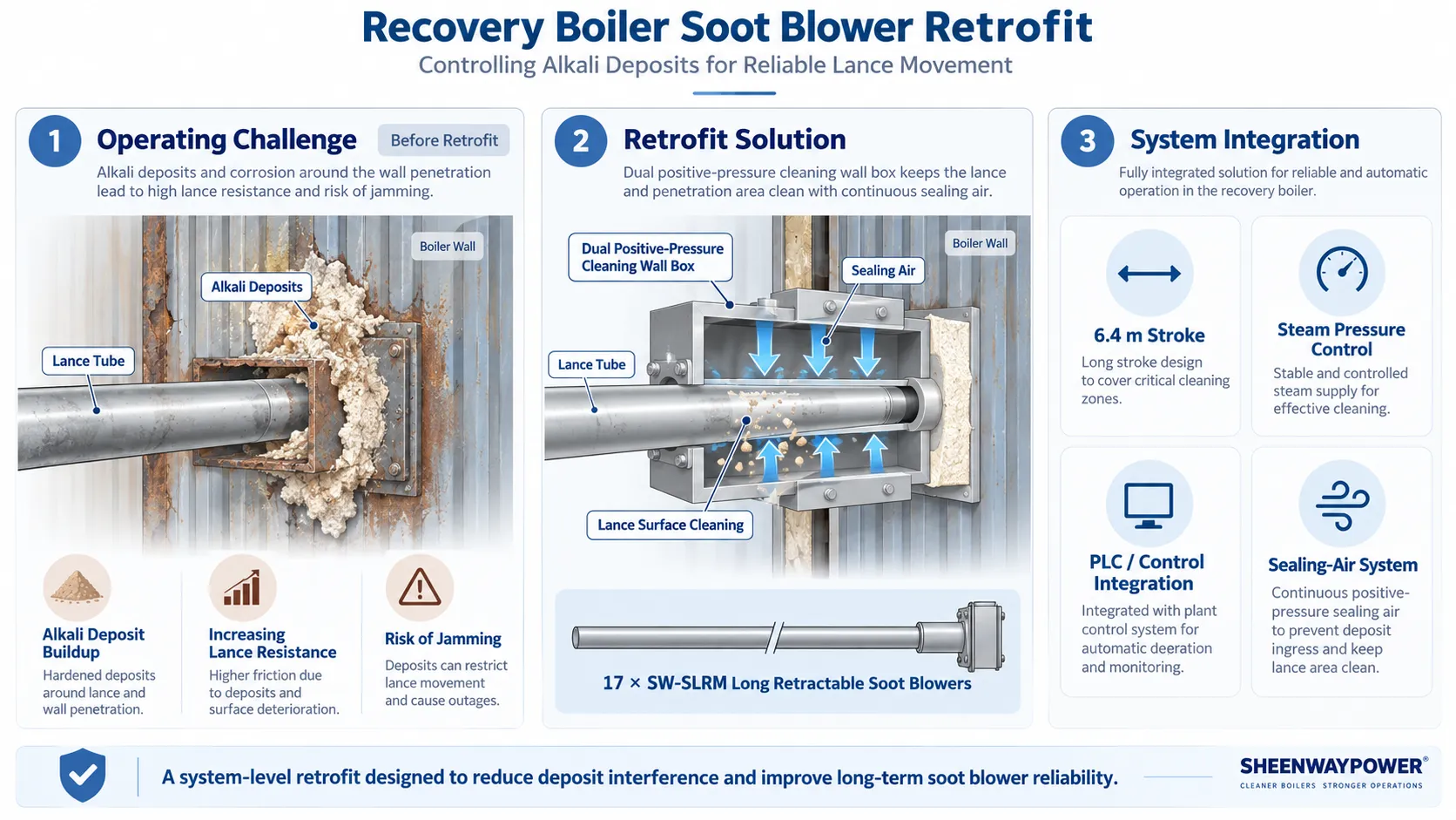
Recovery Boiler Soot Blower Retrofit: 17 Long Retractable Soot Blowers with Dual Positive-Pressure Cleaning Wall Boxes
Unlike many conventional industrial boilers, recovery boilers must continuously handle deposits generated by the chemical recovery process. Alkali-rich deposits can accumulate not only on boiler heating surfaces, but also around soot blower penetrations and lance components, creating additional challenges for mechanical movement, sealing and long-term reliability.
In this retrofit project, SHEENWAY provided a comprehensive upgrade for the steam soot blowing system of a 530 tDS/d recovery boiler at a large pulp and paper manufacturing facility in central China.
The existing boiler was equipped with 31 soot blowers. This retrofit focused on 17 long retractable soot blowers, together with their wall boxes, associated steam piping, sealing-air system and pressure-control equipment.
The project was developed not simply as an equipment replacement, but as a targeted solution to address alkali deposit buildup, lance jamming risk, wall-box leakage, aging equipment and high maintenance requirements.
Project Overview
The recovery boiler had an existing steam soot blowing system used to remove alkali deposits from heating surfaces including:
- Superheaters
- Evaporative heating surfaces
- Economizer sections
Following extended service, part of the existing soot blowing system required comprehensive modernization.
The retrofit included:
- 17 SW-SLRM Long Retractable Soot Blowers
- 17 dual positive-pressure cleaning wall boxes
- Replacement of associated soot blower components
- Steam branch piping modifications
- Sealing-air system upgrade
- Addition of a sealing-air fan
- Sealing-air piping
- Electrical modifications
- Pressure-control system upgrade
- PLC control integration
- Removal of existing equipment
- Installation of new equipment
- Cold commissioning
- Hot commissioning
- Performance verification
- Operator training and technical support
The project-specific soot blower stroke was 6.4 meters, with 360° blowing coverage and an effective cleaning radius of approximately 2 meters.
The boiler steam source was approximately:
- 4.1 MPa
- 400°C
The final soot blowing conditions were selected according to the actual boiler and deposit conditions.
The Core Problem: Alkali Deposits Were Affecting Soot Blower Movement
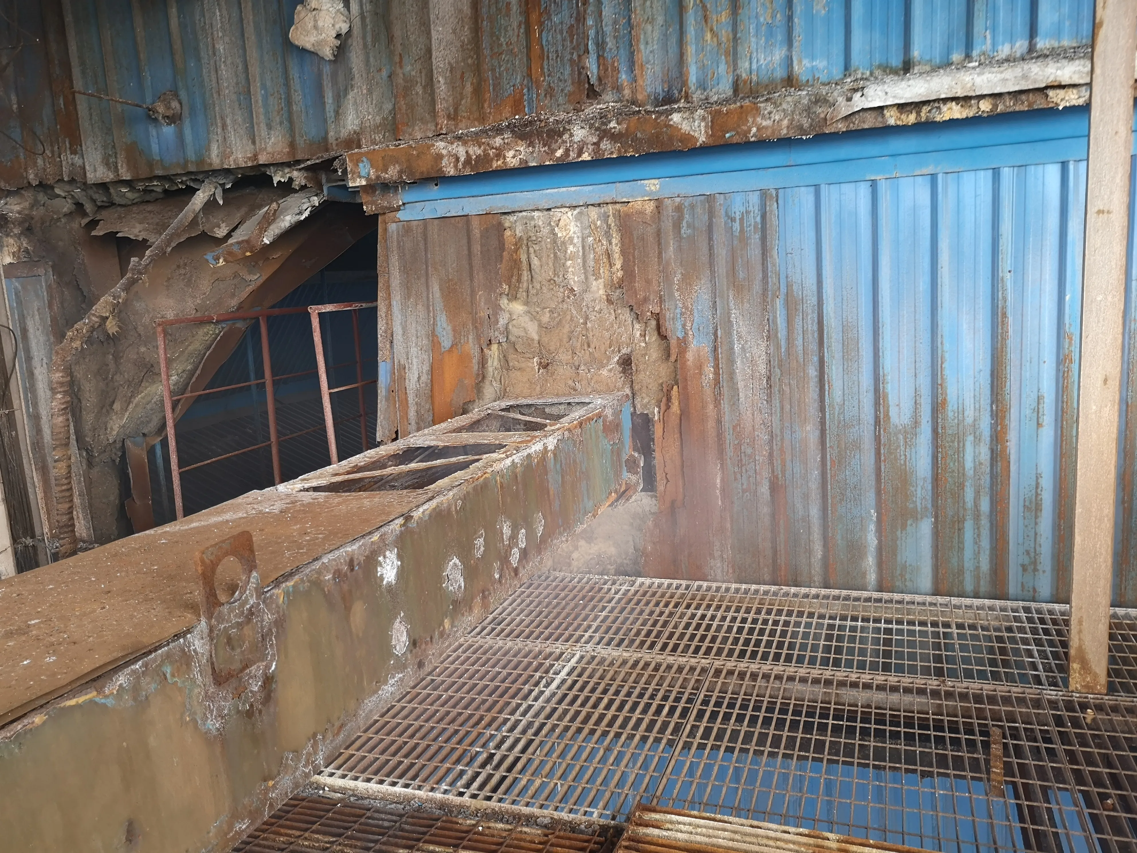
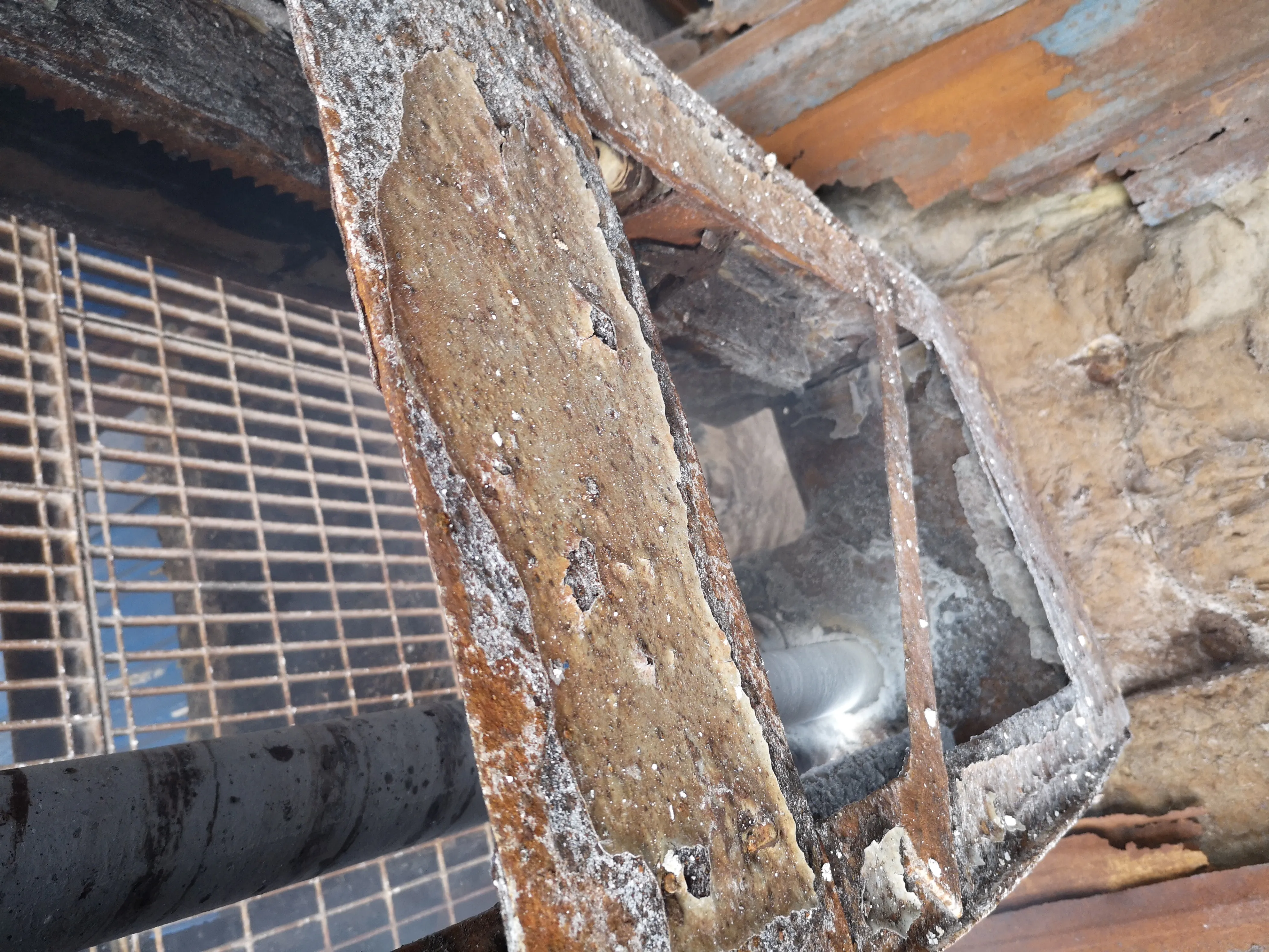
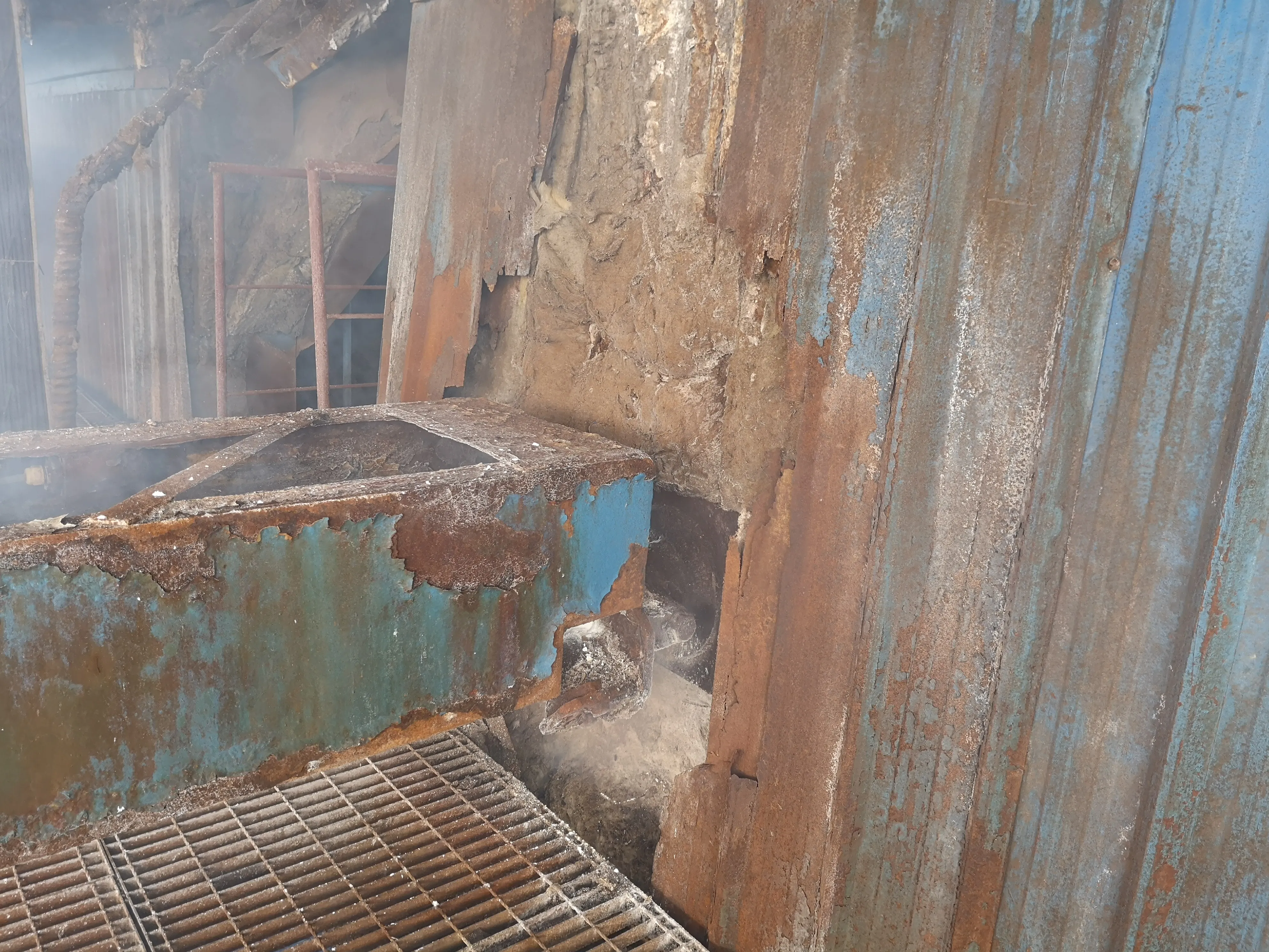
One of the most important engineering issues identified in this project was not simply ash deposition on the boiler heating surfaces.
It was alkali deposit buildup on the soot blower lance itself.
The existing positive-pressure wall box provided sealing protection intended to reduce flue-gas entry into the lance tube and soot blower valve.
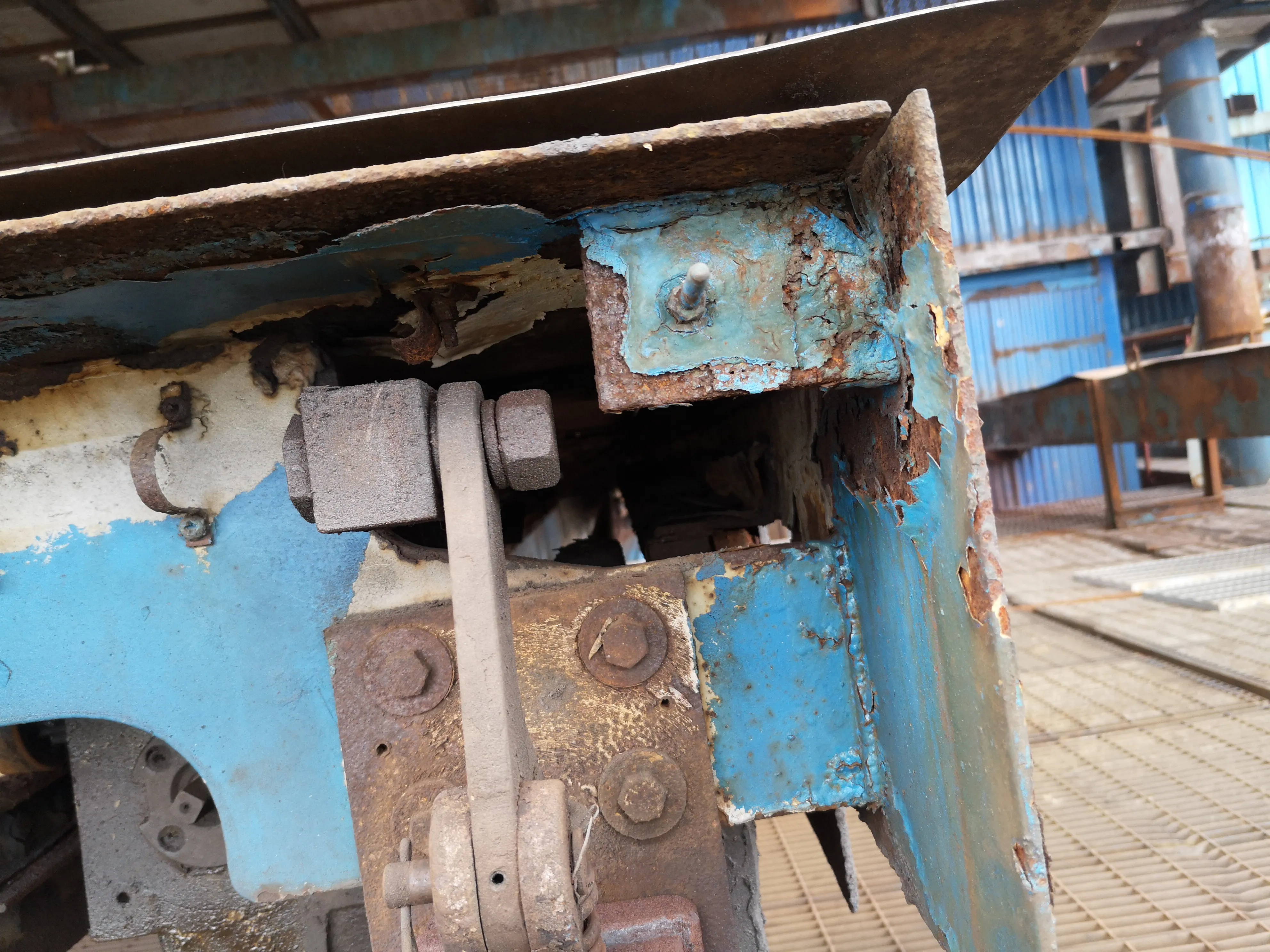
However, the original arrangement could not effectively remove deposits accumulating on the external surface of the lance tube.
Over time, these alkali deposits could become progressively thicker.
As deposit thickness increased, the lance tube could no longer move freely through the wall-box area, increasing resistance during extension and retraction and eventually creating a risk of lance jamming.
For a long retractable soot blower with a 6.4 m stroke, stable mechanical travel is essential.
The retrofit therefore had to address the source of the problem around the wall penetration rather than simply replacing the moving mechanism.
From a Sealing Wall Box to a Cleaning and Sealing System
A key feature of the retrofit was the use of dual positive-pressure cleaning wall boxes.
The new wall-box arrangement was designed to perform two functions simultaneously.
First, positive-pressure sealing helps prevent furnace gas and deposits from migrating into the soot blower lance and valve areas.
Second, the cleaning arrangement helps remove alkali deposits from the lance surface as the soot blower operates.
This reduces the possibility of deposits building up progressively around the lance tube and interfering with its movement.
The objective was to establish a cleaner and more controlled interface between the boiler and soot blower, improving:
- Lance travel stability
- Wall penetration sealing
- Protection against flue-gas intrusion
- Deposit control around the lance
- Long-term mechanical reliability
This is one of the main technical characteristics that differentiates this project from a conventional soot blower replacement.
Why SW-SLRM Long Retractable Soot Blowers Were Used
The project utilized 17 SW-SLRM Long Retractable Soot Blowers with a project-specific stroke of approximately 6.4 meters.
Long retractable soot blowers are used to clean boiler heating surfaces by extending the lance into the boiler while rotating and directing high-energy steam jets toward the required cleaning zones.
After the cleaning cycle, the lance retracts from the boiler.
For this project, the specified operating parameters included:
- Stroke: 6.4 m
- Blowing angle: 360°
- Effective cleaning radius: approximately 2 m
- Travel speed: 0.9-3.5 m/min
- Rotational speed: 9-35 r/min
- Blowing medium: steam
Steam consumption was specified in the range of approximately 50-80 kg/min per soot blower.
These parameters were designed around the recovery boiler's actual cleaning requirements rather than treating the soot blower as a standard catalogue configuration.
Soot Blowing for Recovery Boiler Heating Surfaces
In a recovery boiler, deposit control directly affects the cleanliness of downstream heating surfaces.
The existing soot blowers were used to remove alkali deposits accumulating on sections such as the superheater, evaporative heating surfaces and economizer.
As deposits accumulate, they can interfere with heat transfer and increase the difficulty of maintaining clean heat-transfer surfaces.
Effective soot blowing therefore requires more than simply producing a high-energy steam jet.
The system must also ensure that:
- The lance reaches the required cleaning area
- The lance rotates and travels smoothly
- Steam conditions remain stable
- The wall penetration remains properly sealed
- Deposits around the lance do not interfere with movement
- Cleaning energy is distributed appropriately across the heating surface
The retrofit addressed these requirements as one integrated system.
Sealing-Air System Upgrade
The project also included an additional sealing-air system.
A dedicated sealing-air fan was added, with piping distributing sealing air to each soot blower. Each unit was also provided with an individual manual isolation valve.
This system works together with the positive-pressure wall boxes to maintain a controlled environment around the boiler penetrations.
The sealing-air system was intended to help:
- Reduce furnace-gas leakage through the penetration
- Protect soot blower components
- Limit deposit migration into the wall-box area
- Support the cleaning function of the wall box
- Improve long-term sealing reliability
In a recovery boiler environment where alkali deposits can accumulate around mechanical interfaces, sealing air becomes part of the soot blower reliability strategy rather than simply an auxiliary utility.
Steam Branch Piping Optimization
The retrofit also required modification of the existing soot blowing steam branch piping.
After installation of the new dual positive-pressure cleaning wall boxes, selected steam branch pipes were repositioned to ensure correct alignment between the soot blower inlet valve and the existing steam connection.
This is an important aspect of retrofit engineering.
Even when an existing installation position is retained, changes to wall-box geometry, valve position or equipment dimensions can affect piping alignment.
Forcing the new equipment to fit the original piping geometry can introduce unnecessary stress or installation deviation.
The project therefore adjusted the steam connections around the new soot blower arrangement rather than treating the original piping position as fixed.
Pressure-Control System Upgrade
Another part of the modernization involved the soot blowing steam pressure-control system.
The existing mechanical pressure-reducing arrangement was replaced with a pneumatic regulating valve.
The new control arrangement was integrated into the soot blowing control system, allowing the steam pressure-control function to become part of the wider automated operating architecture.
This provided a more coordinated relationship between:
- Steam supply
- Pressure regulation
- Soot blower operation
- Control logic
- System monitoring
For steam soot blowing, stable pressure control is important because excessive or insufficient blowing pressure can both reduce system performance.
The objective is to supply the required cleaning energy consistently according to actual boiler requirements.
Mechanical Reliability for Long-Stroke Operation
Mechanical reliability was another major design requirement.
The SW-SLRM soot blowers incorporated engineering features intended to support stable long-term operation, including:
- Rigid beam construction
- Enclosed drive arrangement
- Reliable carriage movement
- Protected transmission components
- Lance support and guidance
- Forward and reverse travel control
- Position and limit monitoring
- Appropriate sealing around rotating components
The project also specified a phase-change mechanism to reduce repeated jet impact on exactly the same tube positions during successive blowing cycles.
This helps distribute the cleaning trajectory more effectively and reduces repeated localized impact on boiler tubes.
Control System Integration
Rather than replacing the entire existing plant control architecture, the project retained the existing control system where practical and integrated the upgraded equipment into it.
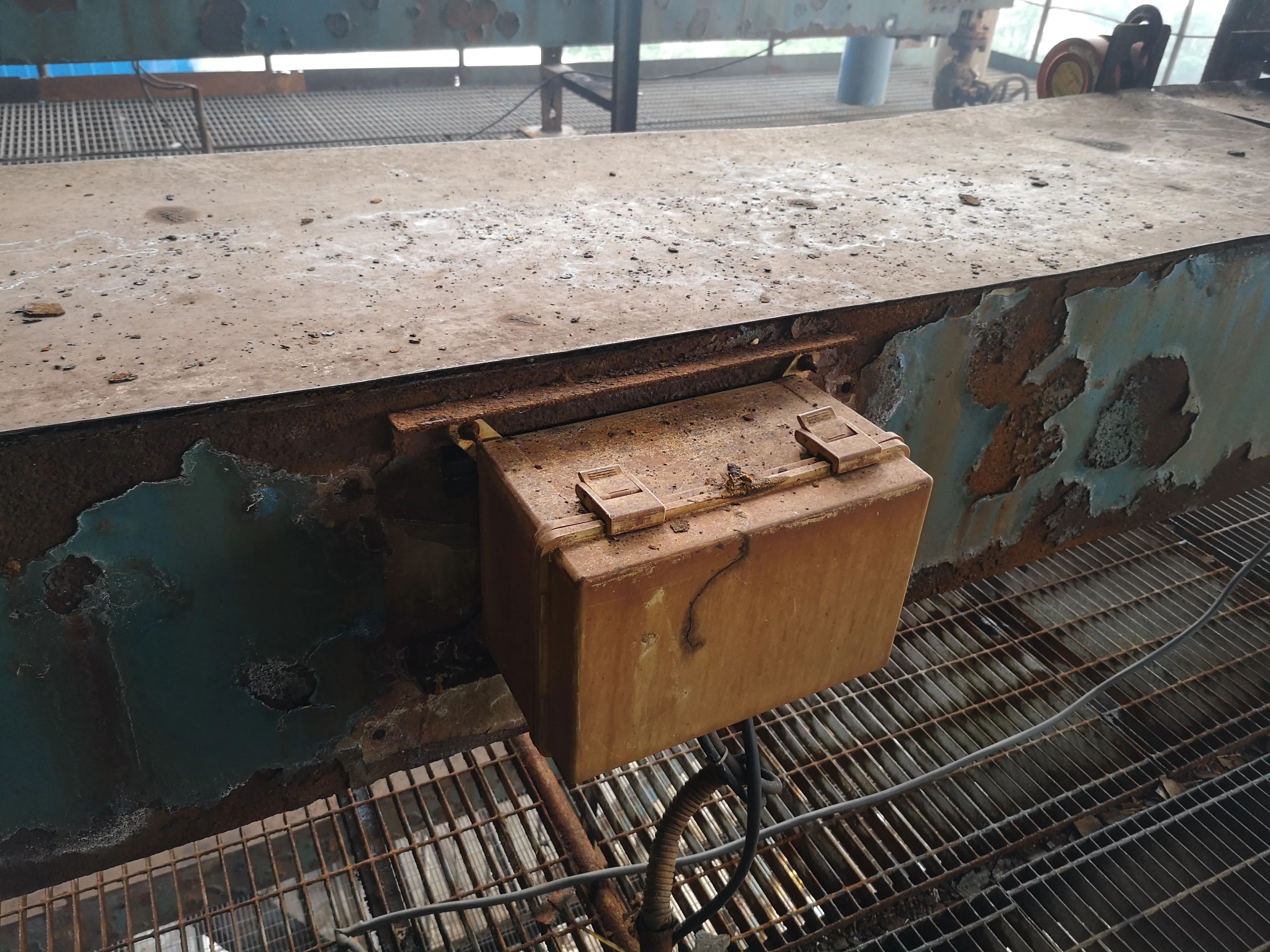
Control cables from the 17 soot blowers were connected to the existing control system, while the new pressure-control equipment and sealing-air functions were incorporated into the updated operating arrangement.
The soot blowers included local controls for functions such as:
- Local / remote selection
- Forward travel
- Reverse travel
- Start
- Stop
- Emergency functions
The system was also commissioned together with the plant-side control equipment to ensure correct interaction between mechanical operation and control signals.
Retrofit Execution Under a Defined Shutdown Window
The project required coordination between equipment manufacturing, delivery and the plant's maintenance schedule.
The overall project period was specified at approximately 65 days.
The execution plan included:
- Materials delivered to site within approximately 45 days after contract effectiveness
- Replacement work for the 17 soot blowers completed within approximately 20 days after the shutdown work notice
- Approximately 3 days for commissioning after equipment replacement
- Performance testing following a period of operating experience
This required careful coordination between engineering, manufacturing, dismantling, installation and commissioning.
For an existing recovery boiler, outage time is limited, making prefabrication, dimensional confirmation and installation planning important parts of the retrofit.
Regional Operating Environment
The project is located in central China in a region with a humid monsoon climate, characterized by warm and humid conditions and substantial seasonal rainfall. Official local climate information describes the region as warm and humid with pronounced seasonal variation and abundant rainfall.
For the soot blower equipment outside the boiler casing, this reinforces the importance of appropriate electrical enclosure protection, sealing and corrosion awareness.
However, the more demanding environment in this particular project came from inside the recovery boiler itself: the combination of heat, alkali deposits and continuous soot blower operation placed significant requirements on wall-box design, lance cleanliness and mechanical reliability.
Installation, Commissioning and Verification
The project included complete technical support for dismantling, installation, commissioning and operator training.
Cold commissioning included checks such as:
- Manual movement of each soot blower
- Valve opening and closing
- Forward and reverse travel
- Limit-switch response
- Motor operation
- Electrical control functions
Hot commissioning then verified operation under actual boiler conditions, including:
- Control-system function
- Steam operating conditions
- Lance travel
- Valve performance
- Wall-box operation
- Sealing-air performance
- Communication with the plant control system
The project also specified subsequent performance verification under operating conditions.
Why This Project Matters
This project is not primarily significant because it involved 17 soot blowers.
Its real engineering value lies in identifying and addressing a failure mechanism specific to the recovery-boiler operating environment.
The original problem involved a chain of interactions:
alkali-rich boiler environment → deposits on the lance surface → increasing deposit thickness → restricted lance movement → risk of soot blower jamming and reduced reliability.
The retrofit therefore did not stop at replacing the soot blower mechanism.
It addressed:
- The soot blower itself
- The wall box
- Lance-surface cleaning
- Positive-pressure sealing
- Sealing air
- Steam piping alignment
- Steam pressure regulation
- Electrical integration
- Commissioning and operating reliability
This system-level approach demonstrates why recovery-boiler soot blowing requires engineering specifically adapted to deposit characteristics and operating conditions.
For SHEENWAY, reliable soot blowing means understanding not only where ash must be removed, but also how the boiler environment affects the soot blower itself.
SHEENWAY Recovery Boiler Soot Blowing Solutions
SHEENWAY provides soot blowing equipment, retrofit engineering and replacement solutions for pulp and paper recovery boilers and industrial boiler applications.
Our capabilities include:
- SW-SLRM Long Retractable Soot Blowers
- Recovery boiler soot blowing systems
- Positive-pressure wall boxes
- Sealing and cleaning systems
- Sealing-air systems
- Steam piping modification
- Pressure-control upgrades
- Retrofit dimensional engineering
- Control-system integration
- Soot blower spare parts
- Installation and commissioning support
For existing recovery boiler projects, SHEENWAY can evaluate the soot blower arrangement, deposit characteristics, lance condition, boiler interfaces, steam conditions and control system to develop a retrofit solution suited to the actual operating environment.
Planning a recovery boiler soot blower retrofit? Contact SHEENWAY to discuss your existing equipment, deposit problems and operating requirements.